Enterprise Wireless Network Design: Beyond Just Putting Up Access Points

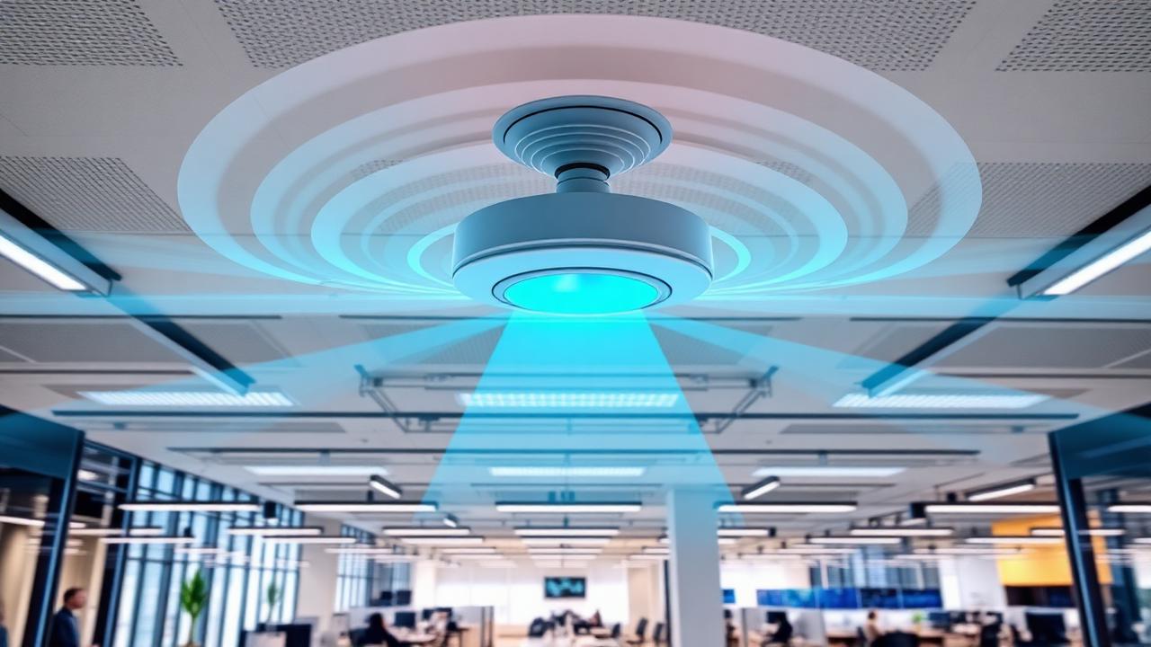
"We put up some access points but the WiFi still doesn't work." I hear this from new clients at least once a week. The frustration is palpable — they've spent money on equipment, paid someone to install it, and the result is a wireless network that drops connections, delivers inconsistent speeds, and can't support the device density their business requires.
The problem is never the access points. The problem is the design — or more accurately, the lack of design. Wireless networking is radio frequency engineering. It's physics. And physics doesn't care how expensive your access points are or how many you've bolted to the ceiling. A poorly designed wireless network with premium access points will always underperform a well-designed network with mid-range equipment.
I've designed and deployed wireless networks in warehouses, hospitals, school campuses, multi-story office buildings, outdoor stadiums, and manufacturing floors. Every environment presents unique challenges. But the principles of good wireless design are universal, and violating them produces universally poor results.
The Site Survey: Foundation of Everything
Before a single access point is mounted, a professional wireless deployment begins with a predictive site survey. This is the most critical step in the entire process, and it's the step that's most frequently skipped — usually because the installer considers it unnecessary or the client considers it too expensive.
A predictive site survey uses specialized software and the building's floor plans to model radio frequency propagation through the specific materials and geometries of your environment. Different construction materials attenuate wireless signals at dramatically different rates:
- ·Standard drywall: 3-4 dB attenuation per wall
- ·Concrete block: 10-15 dB attenuation per wall
- ·Brick: 8-12 dB attenuation per wall
- ·Metal studs or metal mesh: 15-20 dB attenuation
- ·Elevator shafts: Near-complete signal blockage
- ·Glass (standard): 2-3 dB attenuation
- ·Glass (low-E coated): 20-30 dB attenuation (this surprises many designers)
- ·Water (including human bodies): Significant absorption, especially at 5GHz and 6GHz
A site survey accounts for all of these factors and produces a coverage heat map that predicts signal strength and signal-to-noise ratio at every point in the facility. It identifies dead zones, areas of co-channel interference, and regions where adjacent-channel overlap will degrade performance. Most importantly, it determines the optimal number, placement, and configuration of access points to achieve the required coverage and capacity — before any hardware is purchased.
The cost of skipping the survey: A client recently came to us after another vendor installed 24 access points in their 40,000-square-foot office space. The office had an open floor plan with glass conference rooms, a warehouse area with metal racking, and a training center that seated 200 people. The installer placed access points on a uniform grid pattern — one every 1,500 square feet — without considering the dramatic differences in RF propagation across these environments.
The result: excellent coverage in the open office (where they had too many APs creating co-channel interference), adequate coverage in the conference rooms, virtually no coverage in the warehouse (metal racking created faraday cage effects), and catastrophic performance in the training center (200 devices competing for a single AP). We redesigned the network with 18 access points — six fewer than the original installation — and achieved better coverage, capacity, and performance everywhere. The client paid for two installations instead of one because they skipped the survey the first time.
Capacity Planning: The Forgotten Dimension
Coverage and capacity are different things. Coverage asks: "Can a device detect the wireless signal?" Capacity asks: "Can the network support all the devices that want to use it simultaneously?"
A single enterprise access point can cover 5,000-10,000 square feet depending on the environment. But that same access point can only support 30-50 devices at acceptable performance levels. In a conference room with 40 people, each carrying a laptop and a phone, you have 80 devices competing for airtime on a single AP. Performance will be abysmal regardless of how strong the signal is.
Capacity planning determines the device density per area and ensures that enough access points are deployed — with appropriate channel assignments — to support peak concurrent usage. This requires understanding:
- ·Device types: Laptops, smartphones, tablets, IoT sensors, VoIP handsets, digital signage
- ·Usage patterns: Web browsing, video conferencing, file transfers, cloud application access
- ·Peak concurrency: Conference rooms during all-hands meetings, cafeterias during lunch, lobbies during events
- ·Client capabilities: WiFi 5 devices have different airtime requirements than WiFi 6/6E/7 devices
- ·Application requirements: Video conferencing needs 2-5 Mbps per stream; file transfer can consume 50-100 Mbps; IoT sensors need kilobits
Channel Planning: The Art of Not Interfering With Yourself
Radio frequency channels are finite resources. In the 2.4GHz band, there are only three non-overlapping channels (1, 6, 11). In the 5GHz band, there are approximately 25 non-overlapping channels (varying by regulatory domain). WiFi 6E and WiFi 7 add the 6GHz band with an additional 59 channels.
When two access points on the same channel are within range of each other, they create co-channel interference (CCI). Devices can hear both APs but can't decode either clearly — like trying to listen to two conversations at once. CCI is the single most common cause of poor wireless performance in environments with multiple access points.
Proper channel planning assigns non-overlapping channels to adjacent APs in a pattern that minimizes CCI. In a simple environment, this can be done manually. In complex multi-floor buildings, it requires specialized planning tools that account for three-dimensional RF propagation — signals don't just travel horizontally; they propagate through floors and ceilings as well.
Power level management is equally important. Many installers set all access points to maximum transmit power, reasoning that "more power = better coverage." In reality, excessive transmit power increases the coverage overlap between adjacent APs, exacerbating co-channel interference. Proper design uses the minimum transmit power necessary to achieve required coverage — typically 8-14 dBm for 5GHz in office environments.
Common Design Mistakes
1. Consumer-Grade Equipment in Commercial Spaces
Those mesh WiFi systems from the electronics store are designed for homes — 2,000 square feet, 10-20 devices, light usage patterns. Commercial environments need enterprise-grade access points with fundamentally different capabilities: - Higher client capacity: 100+ simultaneous connections per radio vs. 20-30 - Band steering: Intelligently directing capable devices to less-congested bands - Load balancing: Distributing clients across APs to prevent overloading - Centralized management: Single-pane-of-glass configuration, monitoring, and troubleshooting - RADIUS authentication: 802.1X enterprise authentication for secure network access - VLAN assignment: Dynamically placing devices on appropriate network segments based on identity - RF management: Automatic channel and power optimization based on real-time environmental conditions
2. Overloading the 2.4GHz Band
The 2.4GHz band is a wasteland of interference. Microwave ovens, Bluetooth devices, cordless phones, baby monitors, neighboring WiFi networks, and IoT devices all compete for the same three channels. Modern network designs minimize 2.4GHz usage: - Disable 2.4GHz radios on some APs to reduce interference - Reserve 2.4GHz for IoT devices and legacy clients that don't support 5GHz - Set 2.4GHz to minimum power levels - Drive all capable devices to 5GHz and 6GHz through band steering and client minimum RSSI thresholds
3. Ignoring the Physical Layer
Wireless performance is constrained by the wired infrastructure behind it. A WiFi 6E access point can theoretically deliver 2.4 Gbps — but only if the switch port feeding it can deliver that bandwidth. Every access point in a professional deployment needs: - Cat6A cabling minimum: Cat6A supports 10 Gbps at 100 meters, future-proofing for WiFi 7 - PoE+ or PoE++ power: Enterprise APs with multiple radios draw 25-50 watts - Proper mounting height: 8-12 feet in standard office environments, higher in warehouses and gyms - Managed switch with adequate backplane: The switch must have non-blocking backplane capacity to support all connected APs at full throughput simultaneously - Dedicated management VLAN: AP management traffic should be isolated from user data traffic
4. Set-and-Forget Mentality
A wireless network is not a light switch. It requires ongoing monitoring, optimization, and maintenance. RF environments change: new walls are built, furniture is rearranged, neighboring tenants install their own wireless networks, and device populations evolve. What worked perfectly six months ago may be degraded today.
Professional wireless management includes: - 24/7 performance monitoring with alerting for coverage gaps, CCI, and client connectivity issues - Regular RF optimization adjusting channel assignments and power levels as the environment changes - Firmware management keeping AP firmware current for security patches and feature improvements - Client device analysis identifying problem devices, outdated drivers, and misconfigured clients - Quarterly performance reviews comparing current metrics against baseline and SLA targets
The Deployment Process
A proper wireless deployment follows a systematic process:
- 01Discovery: Understand the use case, device types, density requirements, application needs, security requirements, and budget constraints
- 02Design: Create a predictive RF plan using professional tools (Ekahau, iBwave, or Hamina), optimizing for both coverage and capacity
- 03Validation survey: Walk the facility with survey equipment to verify that the predictive model matches reality and adjust if necessary
- 04Install: Mount APs at designated locations, run cabling to spec, configure controllers and management platforms
- 05Commission: Configure SSIDs, VLANs, security policies, QoS settings, and client steering parameters
- 06Post-installation survey: Walk every area with survey equipment to verify coverage, capacity, and roaming performance
- 07Optimize: Adjust channel assignments, power levels, and AP configurations based on post-installation survey data
- 08Monitor: Deploy ongoing monitoring with alerting, reporting, and regular optimization cycles
The process takes 2-6 weeks depending on facility size and complexity. The investment pays for itself through reduced support tickets, improved employee productivity, and elimination of the "WiFi doesn't work" complaints that consume disproportionate IT resources.
The Bottom Line
Wireless networking is infrastructure, not an accessory. It deserves the same engineering rigor as your electrical system, your HVAC system, or your structured cabling plant. Organizations that treat wireless as a commodity — buying the cheapest APs and bolting them to the ceiling without design — will spend more on troubleshooting, support, and rework than they would have spent on doing it right the first time.
Invest in the survey. Invest in the design. Invest in enterprise-grade equipment. And invest in ongoing management. Your employees, your customers, and your business outcomes will thank you.